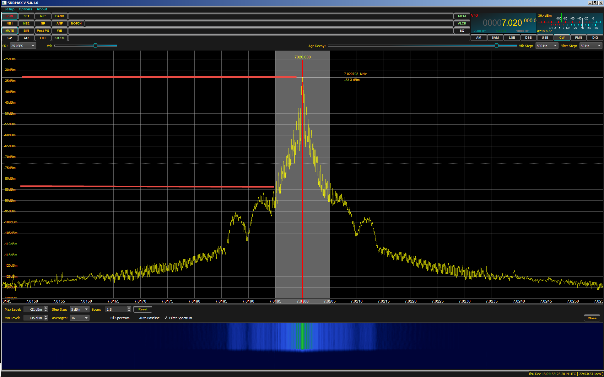
These parts of the signal "dance" in and out, showing aliasing due to improper input filtering and/or reconstruction from samples. I tested a 21.5Mhz oscillator and you can see in the screenshots that the main component amplitude is shown correctly, but it has problems with some high frequency harmomics (captured without problems with the Rigol). Signals up to 20Mhz bandwidth seem to work flawlessly. Bandwidth: - I don't have required equipment to test this properly, but i tested some signals I had at hand on a circuit. Normal/Auto trigger mode: - Works perfectly, always triggered at the right edge, no jitter, nor triggered at the wrong point. Anyway, what can you expect from a probe at this price point? - Single trigger mode: - Works perfectly, never missed a pulse (needs more testing to be absolutely sure about this). (I fixed it, i'll post pictures about how). Coupled with the fact that the internal ring has not a tight fit with the scope female ground causes sometimes a bad signal reading. In my case, it had a quality defect (maybe it's common for this cheap probes), the outer metal ground "ring" sometimes does not make a good contact with the internal ground ring. Quality of included probe: - It's a cheap P6100 X1/X10 and it comes already compensated for the scope. The manufacturer seems to own this youtube channel: - They also seem to have a downloads page with documentation and updated firmware with instructions!: - Internal TF card slot for unknown purpose (Investigation pending ). Go to "set" menu and long press the "V" button, in my case it shows v1.1.8. I found a secret menu that seems to show the firmware version. Settings are saved/remembered when powered of: Some of these cheap scopes reset the settings (Time base, coupling.) each time they are powered off, maybe to allow easy reset for novice users. Reference waveform: - A reference waveform can be saved, but unfortunately it's locked to the current time base, if time base is changed, the reference is still freezed with the old time base, it's just a background image. This works very similar to a good scope (like my Rigol), you can even capture the signal at a time base and zoom in or out with the time base (of course, limited to the sample memory available). When transferred to PC, files are always re-numbered from newest to oldest, this means that if you take some screenshots and copy them to your PC, if they are not removed from the device, next time the same screenshots will have a different name. It can save screenshots to internal memory and can be transferred using USB (Device name is "F1C100S XiaoTaoQi Disk USB Device"), but some things could be handled better: - There is no confirmation for deletion. Protruding BNC: Big plastic BNCs (Like my Rigol ones) can be used, but you have to force the included rubber protection out of the way. No indication is shown about charging on screen, it's indicated by a small led near the USB.

Charged without problems in less than 1 hour (not timed). Battery runtime has not been timed precisely, but i used it for several hours each day, for a total of about 5-6hours. Tested, output waveform amplitude is 3V (min 0V, max 3V) - Reduced number of buttons: Second button functions are very well designed and I don't miss any extra button (see attached image from the manual).

Square wave generator: Adjustable: 0-2Mhz. Hardware (Information from the internet, I will check it as soon as I open it): FPGA LATTICE LCMXO2-1200HC-5TG100I CPU Allwinner F1C100s ARM926EJ-S (ARMv5TE) up to 533MHz - 32MB of embedded DDR SDRAM. Using the term bandwidth to describe time maps more closely (in my opinion) to the original definition, than the current definition describing data capacity does.I bougth a DSO1511E, and I promised to put in this forum a mini review. Being "out of bandwidth" would indicate that you do not have enough unallocated "bands of time" in your day to complete the task. Now, if we think of the tasks that we perform throughout the day as consuming separate "bands" of time, then the term makes perfect sense.

(Cable and Satellite communications do use EM bands for their data, whereas dial-up internet uses sound waves transmitted over copper.) This term was borrowed for use in telecommunications to represent the total capacity of any channel, regardless of whether it was utilizing a specific EM band or not. Each FM radio channel occupies about 100 kHz of this band. For example, the US FM Radio band is allocated from 87.5 to 108.0 MHz. Wider frequency bands allow more "channels" of data to flow through. Bandwidth was originally used to mean the width, in Hz, of an Electromagnetic Spectrum "band" (a contiguous interval of frequencies) that is allocated to a particular use.


 0 kommentar(er)
